logo for matrixlab-examples.com
leftimage for matrixlab-examples.com

Combinational logic - Basic Applications of Boolean Gates

Experiments with electronic gates


Logic circuits can be divided into two major sections:
combinational logic and sequential logic. The main difference is that the first type of circuit logic doesn’t depend on time or sequence of movements, and the second type of logic does.


A
clear example to understand this difference can be illustrated by showing the two locks below:


illustration for combinational logic sequential logic illustrated
Combinational Logic Sequential Logic

The lock on the left has four discs that can be rotated separately. When the notches are aligned, the metal hook is released. The only one condition needed is that the appropriate four notches are aligned, no matter if the left disc is set before the one on the right. The lock will open if you have the correct combination. 

On the contrary, the lock on the right has only one knob, and the combination could be 3cw – 52ccw – 20cw. This means that one must first get to number 3 going clockwise, then to 52 counterclockwise, and finally get to number 20 clockwise. If you use the same numbers in different order, the lock won’t open. This is a sequential lock, a correct sequence is important. 

Due to its stability, reliability, low maintenance and ease at reading digital displays, these days everything is going the digital way. 

Logic circuits can be simulated with the so called boolean or logic gates. This is kind of Digital Electronics 101... 

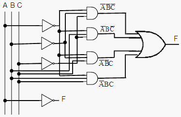
Let’s say that we’d like to find out the behavior of the following combinational circuit:
 

combinational logic - example with logic gates 

 
We can create an m-file to effortlessly solve the logic circuit, like this:

function f = combination(x)
% x(1) = A
% x(2) = B
% x(3) = C
% Symbol ~ is used for NOT gates 

% We have 4 logic-AND gates
and1 = ~x(1) & ~x(2) & ~x(3);
and2 = ~x(1) & x(2)  & ~x(3);
and3 = ~x(1) & ~x(2) & x(3);
and4 = ~x(1) & x(2)  & x(3); 

% We have 1 logic-OR gate
f = and1 | and2 | and3 | and4; 


We can test our function for this specific example of combinational logic:
 

% These are all the possible combinations for 3 inputs
M = [ 0 0 0
      0 0 1
      0 1 0
      0 1 1
      1 0 0
      1 0 1
      1 1 0
      1 1 1]; 

% We give all the combinations, one at a time 
for i = 1 : 8
    comb_log(i) = combination(M(i, :));

end 

% We display the results
comb_log


The results are: 

comb_log =  1     1     1     1     0     0     0     0


If you make some analysis using the DeMorgan laws, you can conclude that this function can also be simplified to F = not(A), and you can visualize it from the results...

This means that we have not only a MATrix LABoratory, but we've got also a circuit logic simulator!
 

 From 'Combinational Logic' to home

 From 'Combinational Logic' to 'Boolean Algebra'

Top

And Gate

Or Gate

Not Gate

Boolean Operators

Xor Gate


footer for combinational logic page