
Power Factor Correction CapacitorsIn this article we are going to develop an algorithm or method to find out capacitors for power factor correction. This is the simplified example that we propose for this matter...
Our task is to find the
capacitor C to get a corrected PF =
0.92. We know that AC power
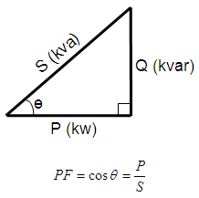
flow has three components: real or
active power P, measured in watts (W); apparent power S, measured in
volt-amperes
(VA); and reactive power Q, measured in reactive volt-amperes (var).
The
following right-triangle describes the relationship for those three
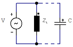
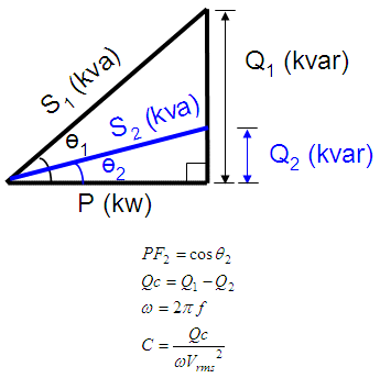
components.  If we add a capacitor in parallel, the reactive power of the system will change (decrease). The difference between the original reactive power Q1 and the resulting reactive power Q2 (after placing the capacitor) is called Qc. The final capacitor is a value depending on the reactive power Qc (in var), the frequency (in Hz) and the voltage at the load (Vrms). This diagram shows the idea and we present the formulas.
clear all, clc %
Known data: voltage source, frequency, starting power factor %
We calculate the initial angle, apparent and reactive powers %
We calculate the final angle, apparent and reactive powers %
We calculate the difference in reactive powers %
We express the capacitor in microfarads The results shown in the
command window are: Vrms = 220 From 'Power Factor Correction Capacitors' to home From 'Power Factor Correction Capacitors' to Electrical Calculations
|


